What size wire do I need for 12 volts?
The bigger of two answers. One is ampacity: the current the cable can carry without its insulation cooking. The other is voltage drop: how many of your 12 volts the cable burns as heat before they reach the device. Both have to be checked, the answer is whichever needs the thicker cable, and on a 12 V system that's almost always the drop, by two to six sizes. Voltage changes the picture fast. At the same current, twice the voltage allows twice the drop in volts, so a 24 V run needs half the copper cross-section: the 30 A, 20 ft DC-DC run further down goes from 2 AWG at 12 V to 6 AWG at 24 V. At the same power the current halves as well, and the cross-section falls to a quarter. That's why the chart above is for 12 V only. What four common RV runs look like:
| Run (12 V, 3%) | Ampacity alone says | …and would drop | Right answer | Sizes up |
|---|---|---|---|---|
| Fridge, 8 A, 20 ft | 18 AWG | 21.2% | 8 AWG | 5 |
| DC-DC charger, 30 A, 20 ft | 14 AWG | 31.4% | 2 AWG | 6 |
| Converter, 55 A, 6 ft | 10 AWG | 6.8% | 6 AWG | 2 |
| Inverter, 2,000 W (174 A), 10 ft | 2 AWG | 5.6% | 2/0 AWG | 3 |
One-way runs; drop computed on both legs. Ampacity from ABYC E-11 Table VI-A (105 °C, outside engine spaces); resistance from NEC Chapter 9 Table 8 at 75 °C. "Sizes up" counts steps on this page's gauge list from the ampacity answer to the drop answer.
NEC 310.16, the ampacity table in most wiring references, describes building wire bundled in conduit inside a 30 °C wall. RV and marine battery cable is 105 °C-rated and runs in free air, and ABYC E-11 (the boat standard, which the RV trade borrows for DC) rates it accordingly: 2 AWG is 210 A in E-11's Table VI-A against 115 A in the NEC's 75 °C column. Using the NEC figure pushes every answer one or two sizes up and hides the reason 12 V cable is thick, which is the drop. Resistance comes from the NEC's Chapter 9 Table 8, because a conductor's ohms don't depend on the standard it's installed under; 12 AWG is 1.98 Ω per 1,000 ft there, the figure Mike Holt's voltage-drop course works from too.
What size cable for a 2,000 watt inverter?
Start from the current: 2,000 W through a 90% inverter on a 12.8 V lithium bank is 174 A. That's ampacity for 2 AWG, and at a 10 ft run 2 AWG loses 5.6% of your voltage, so the answer is 2/0 AWG. Inverters are the one place the run is short and the current enormous, and the length decides more than the wattage does:
| Inverter | Amps running / near empty | 3 ft | 5 ft | 8 ft | 10 ft | Fuse |
|---|---|---|---|---|---|---|
| 1,000 W | 87 / 93 A | 6 AWG | 4 AWG | 2 AWG | 2 AWG | 125 A |
| 1,500 W | 130 / 139 A | 4 AWG | 2 AWG | 1 AWG | 1/0 AWG | 175 A |
| 2,000 W | 174 / 185 A | 2 AWG | 2 AWG | 1/0 AWG | 2/0 AWG | 225 A |
| 3,000 W | 260 / 278 A | 1/0 AWG | 1/0 AWG | 3/0 AWG | 4/0 AWG | 350 A |
12 V lithium, 90% efficient, full continuous output. Running current at the bank's 12.8 V nominal; the 3% drop judged against the 12 V system voltage (0.36 V, the way ABYC E-11 figures it); cable rated for the current at 12.0 V near empty. One-way run from the bank. Fuse = 125% of the running current, up to the next standard size; where that's over the 5 ft cable's rating, the tool names the next size up. The inverter manual's cable and fuse figures win where they're larger.
The current is where most estimates go wrong. Dividing 2,000 W by 12 V gives 167 A, but the inverter loses 10–15% on the way, so the bank supplies more than the outlet delivers, and current rises as the battery voltage falls. On a lead-acid bank at 85% the same inverter pulls 196 A at 12 V and 224 A at the 10.5 V where most inverters shut down, 34% more than the simple division. The tool figures the running current at the bank's nominal voltage, judges the drop against 12 V as ABYC does, and rates the cable for the current near empty. Moving the inverter closer to the batteries is still the cheapest fix of all: halve the run, halve the drop. The inverter size calculator works out the draw for the loads you run and checks the bank can supply it, and the AC-on-batteries calculator does the same for the biggest load most rigs ever put on an inverter.
On the 10 ft inverter run, 2 AWG is legal for 174 A and drops 5.6% of 12 V, about 0.7 V, or 117 W warming the cable at full load. The inverter sees the lower voltage too and pulls more current to make up for it. On a lead-acid bank, which already sags under a big load, those lost volts bring the low-voltage alarm long before the bank is empty. 2/0 AWG cuts the loss to 58 W. Undersized 12 V cable seldom fails with smoke; the usual symptom is an inverter that shuts down early on a battery that tests fine.
Is wire length one-way or round trip?
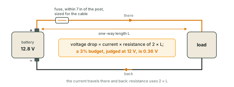
Enter it one-way here. Current goes out on the positive and comes back on the negative, and both legs lose voltage, so the drop is computed on twice the distance from the battery to the device. ABYC E-11 measures the same loop, "from the positive power source connection to the electrical device and back to the negative power source connection." Calculators differ on which length they want, and a one-way figure typed into a round-trip box sizes the cable for half the loss, so check the label before you trust the gauge. This page asks for one-way and doubles it in the math, where you can see it. The negative matters as much as the positive: a skinny ground back to a chassis bond is the same resistance in the same loop.
What size wire for solar panels to the charge controller?
The run from roof to controller carries the array's voltage, not the battery's, so the way the panels are wired decides the gauge. Two 200 W panels in series run at about 40 V and 10 A; in parallel, at 20 V and 20 A. Same watts, and the series pair can use cable three sizes thinner for the same 3%, which is the main reason MPPT controllers took over RV roofs. The cable's rating follows NEC 690.8, which applies 125% twice: once to turn the panels' short-circuit current into the circuit's maximum current, and again to size the conductor for it, so the cable carries 1.56 × Isc (EC&M's walk-through of the section). Over a 20 ft run from roof to controller:
| Array | Circuit | Operating A | Rated for (Isc × 1.56) | Cable |
|---|---|---|---|---|
| 2 × 200 W in parallel | 20 V | 20 A | 34.4 A | 6 AWG |
| 2 × 200 W in series | 40 V | 10 A | 17.2 A | 12 AWG |
| 4 × 200 W, 2 in series × 2 | 40 V | 20 A | 34.4 A | 10 AWG |
| 4 × 200 W in parallel | 20 V | 40 A | 68.8 A | 4 AWG |
A typical 200 W panel: Vmp 20 V, Isc 11 A; read yours off the sticker on the back. Drop at the operating current (watts ÷ Vmp), 3%; cable rated for Isc × 1.25 × 1.25 (NEC 690.8(A) and (B)); the fuse is 125% of Isc × 1.25. Series strings need an MPPT controller rated for the array's open-circuit voltage on a cold morning; a PWM controller wastes the extra volts.
The controller-to-battery leg is a separate run at battery voltage and the controller's full output current: a 40 A controller two feet from the bank is its own line in the tool. The solar calculator sizes the array and the controller.
What size wire for a DC-DC charger?
A DC-DC charger sits on the longest heavy run in a rig: the truck's battery to the trailer's, or the alternator at the front of a motorhome to a house bank at the back. A 30 A charger over 20 ft needs 2 AWG to hold 3% at 12 V, against the 14 AWG its current alone would suggest, and some chargers' terminals won't take cable that big. Mount the charger near the house bank and run the long leg on the input side, where a few percent of drop only costs the charger some input headroom. How much the charger adds to a drive is the charge time calculator's question.
| Charger | 10 ft | 15 ft | 20 ft | 25 ft |
|---|---|---|---|---|
| 20 A | 8 AWG | 6 AWG | 4 AWG | 4 AWG |
| 30 A | 6 AWG | 4 AWG | 2 AWG | 2 AWG |
| 40 A | 4 AWG | 2 AWG | 2 AWG | 1 AWG |
| 50 A | 4 AWG | 2 AWG | 1 AWG | 1/0 AWG |
12 V, 3%, one-way run at the charger's rated current. On a 24 V house system the 30 A / 20 ft run drops to 6 AWG. The 7-pin trailer plug's charge wire (usually 10–12 AWG over 20+ ft) is why a trailer barely charges from the truck without one.
What size fuse, and where does it go?
The fuse protects the cable, not the device, so it's sized against the cable and goes at the battery end: 125% of the continuous current, rounded up to a standard size, and, in ABYC E-11's words, never above "the maximum current carrying capacity of the conductor being protected." When those collide (2,000 W on a lithium bank over 5 ft: 2 AWG holds the drop and is rated 210 A; its fuse wants 225 A) the result names both ways out: the next cable up, or a smaller fuse that may open at sustained full load. A fuse bigger than the cable's rating leaves the cable as the weakest part of the circuit, and that's the part that burns.
Where: within 7 inches of the battery terminal, measured along the cable, is ABYC's rule (72 inches if the cable runs straight from the battery inside a sheath or enclosure the whole way). On a lithium bank the fuse also has to be able to stop a short: a LiFePO4 battery can deliver thousands of amps into a dead short, and the fuse's interrupt rating has to exceed that. A Class T fuse is rated to interrupt 20,000 A at 125 V DC; an ordinary ANL is rated far lower. That's why lithium installs put a Class T at the bank, or an MRBF on the terminal post.
Copper, welding cable, or CCA?
ABYC requires stranded copper, and every number on this page assumes it. The cable ABYC compliance calls for is UL 1426 boat cable, such as Ancor's tinned battery cable, rated 105 °C, which is the rating this page's ampacity column is built on; the tinned strands resist corrosion. Welding cable is fine-stranded and flexible too, but it's built to a different standard and its rating depends on the line. Southwire's Royal Excelene has EPDM insulation rated 105 °C and is not UL listed; its Royal Super Excelene is UL listed, with a CPE jacket rated 90 °C. Neither is UL 1426 boat cable. A 90 °C cable belongs in E-11's 90 °C column, where 6 AWG is 100 A instead of 120, so check the jacket before you rely on the 105 °C figure. The trap is copper-clad aluminum, sold cheap as "battery cable" and in amplifier kits under the same gauge numbers. Aluminum conducts worse than copper, so a CCA cable marked 4 AWG has noticeably more resistance than copper 4 AWG; the usual rule is to treat it as two sizes smaller, and it doesn't hold a crimped lug the way copper does. If the price per foot looks like a bargain, check the jacket for "CCA".
Sources
- NEC 2014: Chapter 9 Table 8, Conductor Properties, NFPA 70, reproduced by BuildMyOwnCabin: DC resistance of stranded copper at 75 °C, ohms per 1,000 ft
- Voltage-Drop Calculations, Unit 8 (sample pages), Mike Holt Enterprises: Chapter 9 Table 8 resistances and the DC resistance formula
- E-11 AC and DC Electrical Systems on Boats (excerpts), American Boat & Yacht Council, excerpt published by Paneltronics: Table VI-A ampacity of single conductors (105 °C, outside and inside engine spaces); 3% and 10% drop on the round-trip length at nominal 12 V; fuse within 7 in of the battery
- Part 1: Choosing the Correct Wire Size for a DC Circuit, Blue Sea Systems: ABYC E-11 wire sizing for 105 °C wire. Returns 403 to automated fetchers; opens in a browser
- Solar Photovoltaic Systems, Part 1, EC&M (Mike Holt): NEC 690.8: circuit current = Isc × 125%, conductors sized for 125% of that
- Ancor Catalog 2024, page 11: Premium Battery Cable Assemblies, Ancor: UL 1426 tinned copper boat cable, 105 °C
- SPEC 70305: Royal Excelene Non-UL Welding Cable, Southwire: EPDM insulation, 105 °C, not UL listed
- SPEC 70300: Royal Super Excelene Welding Cable UL, Southwire: CPE jacket, −50 to 90 °C, UL listed